
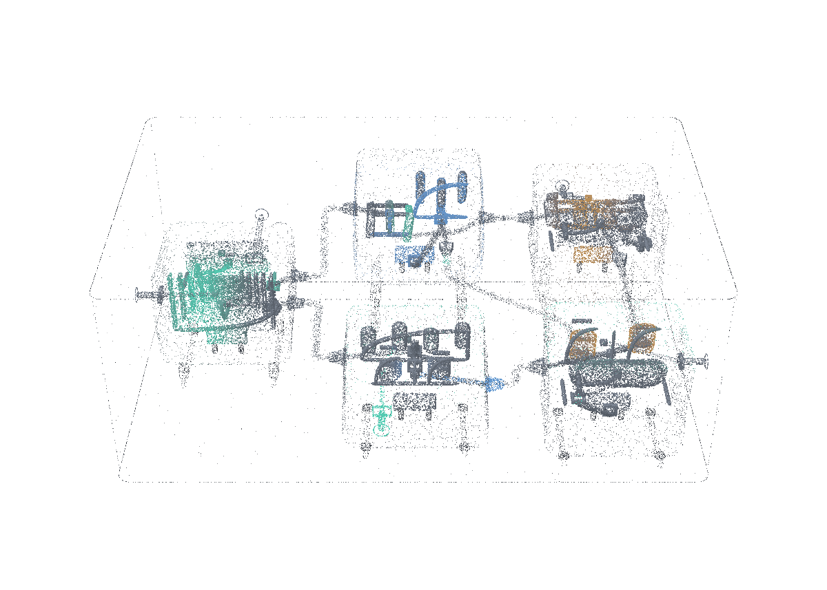
From a device to a useful compute site

A rack is only useful if the whole site can support its workload.

Containment, physical limits and workload calculation. An illustrative design calculation under explicit equipment and workload assumptions.
Loading model
Technical descriptionsInteractive model unavailable. The static illustration and descriptions remain available.
Hierarchical configuration
Place devices within racks, rooms, buildings and plot with sourced assumptions.
Technical data

Inputs

Tagged equipment and site assumptions.

One explicit revised equipment assumption; preserve the original baseline.

Transformation

Place devices within racks, rooms, buildings and plot with sourced assumptions.

Retained state and outputs

Fit, aisle, mass, floor load and site assumptions.

Original configuration and changed input remain identifiable.

Constraints

Physical fit and site assumptions retain their source and units.

Electrical and thermal propagation
Keep distinct power bases and propagate losses, heat and cooling demand.
Technical data

Inputs

Equipment/power assumptions with containment context.

Transformation

Keep distinct power bases and propagate losses, heat and cooling demand.

Retained state and outputs

Nameplate, provisioned peak and utilization basis.

IT heat, conversion losses and facility demand.

Constraints

Nameplate, provisioned peak and utilization are different power bases.

Inference workload model
Derive memory and throughput bounds from the workload and selected equipment.
Technical data

Inputs

Selected capacity and placement.

Model shape, precision, context and concurrency.

Transformation

Derive memory and throughput bounds from the workload and selected equipment.

Retained state and outputs

Weights, workspace, KV memory, precision and concurrency.

Compute/memory bounds and selected utilization assumptions.

Constraints

An infeasible memory requirement prevents an operating-energy result for that configuration.

Time and energy scenario
Balance load, supply, storage and grid under the selected time basis.
Technical data

Inputs

Calculated facility load under the selected power basis.

Duration/weather/supply/storage assumptions.

Transformation

Balance load, supply, storage and grid under the selected time basis.

Retained state and outputs

Load, generation, exchange, shortfall and storage state.

Base/low/high inputs and their source quality.

Constraints

Time-based supply and storage remain balanced, including shortfall.

Constraint and alternative comparison
Join physical and workload results and expose the binding constraint.
Technical data

Inputs

Electrical and thermal feasibility.

Memory feasibility and workload bounds.

Calculation with its time basis, not an observed operating result.

Transformation

Join physical and workload results and expose the binding constraint.

Retained state and outputs

Feasible, failed and unresolved results.

Units, method, input lineage and comparison basis.

Constraints

Calculated feasibility is an illustrative evaluation, not commissioned hardware performance.

An illustrative design calculation under explicit equipment and workload assumptions.

Additional mechanisms are described in the technical reference.

Place the equipment. Follow its physical demand.

A proposed compute-site scenario showing the relationship between equipment, energy and inference.

  1. Place the equipment

    A planner assembles devices into racks and checks fit, clearance and floor loading in the intended room.

  2. Follow the power and heat

    Component demand, PSU losses, redundancy and cooling contribute to facility requirements. The calculation keeps its distinct power bases.

Test the workload against the whole site.

Model weights and KV cache must fit the proposed memory and placement. Batch, concurrency and compute bounds determine the scenario’s service limits.

  1. Bring in the workload

    Model weights and KV cache must fit the proposed memory and placement. Batch, concurrency and compute bounds determine the scenario’s service limits.

  2. Compare the operating case

    An hourly energy scenario adds grid limits, generation and storage assumptions. The planner compares alternatives with the same inputs and opens the methods behind the limiting factor.

Within the Naevum ecosystem.

Connected system

Explore the system

The product page explains its specific mechanisms and operating scope.

Connected system

Explore the system

The product page explains its specific mechanisms and operating scope.

Connected system

Explore the system

The product page explains its specific mechanisms and operating scope.

Technical referenceFurther context

What could these mechanisms make possible for you?

Discuss a capacity scenario